
Mainsprings, their function and how they are made.
Isochronism is the primary goal of every modern timekeeper. It is the characteristic of generating a constant, uniform period of vibration, to be able to assure a consistent rate of time. Although every part of a movement is important to achieve this, much of what can be made following the mainspring and barrel would be rendered ineffective if the mainspring is not well made.
Every mechanical watch requires a power source to drive the wheels that lead to the regulatory organ, which is in 99.9% of watch movements an oscillating balance wheel. The power source is a mainspring, wound either manually by hand through a winding crown, or by an automatic winding system incorporated into the watch movement. Although there are always exceptions to every rule in horology, there exist two fundamental types of mainspring. Those that when fully wound are blocked from turning, made for manually wound movements, and automatic mainsprings. Automatic mainsprings have a longer bridal fixed at their end which push against the inside of the last turn of the spring, approximately 20% thicker than the rest of the spring. This long bridal allows the mainspring to slide on the inside of the barrel (where the mainspring lives) once the spring is fully wound. This allows the automatic mechanism to continue to turn, continuing to wind the fully wound spring without causing any damage.

On the upper left a manual wind mainspring. On some early automatic calibres manual wind mainsprings were used, coupled with a system that would stop the rotor from moving when the mainspring was fully wound. On the right an automatic mainspring with long bridal and below them both a mainspring stocked in an aluminium ring.
Mainsprings originally replaced weights used to power clocks to be able to render them both smaller and portable. They first appeared (approximately) in 15th century European clocks and by the 16th century in pocket watches. Since their conception, as with all elements found in horology from the most simple to complex, there have been considerable technological steps forward in their manufacture and efficiency.
Traditionally there were basic proportions by which mainsprings were made in relation to the barrels they sat into. These proportions were defined by the internal diameter of the barrel and the diameter of the barrel arbour (the arbour is the axel that winds the mainspring in the centre of the barrel, hooking onto the inner coil of the mainspring). These would lead to on average 8 turns of the barrel arbour until the mainspring was fully wound. Today however, with the development in watchmaking and the influences of modern construction and manufacturing techniques, there are many variations leaving the classical approach behind. This departure makes what is a complex component to produce, a far greater challenge to make. These variations may be due to the height of the mainspring which can be as small as 0.6mm or, to wider than conventional barrels, with mainsprings with an extended length of over 2 meters made to increase power reserve. The power reserve is the complete period of time the watch will run for after a single complete winding of the mainspring.
The reasons for the difficulty in the manufacture of the mainspring are on many levels. Apart from the goal to reduce the potential fatigue a spring will incur during its lifetime, the lubrications used to assure its correct function are critical to its long term consistency. The manufacturing process requires foresight taking into consideration these and many other factors. The mainspring converts the power it receives either from the operators manual winding, or by gravity’s effect on the rotor. Releasing the power accumulated in the barrel through a series of gears and delivers it in the most consistent and 'even' transmission possible. The largest tension and potential areas of friction in the watch movement, are directly associated with the barrel and the winding mechanism that drives it.
The process shown below illustrates some 13 steps involved in the process of making the mainsprings. It is non-exhaustive and certain parts of the process are kept confidential. The full process, of which there are many derivatives depending on quantity to be made and the specifications required involves considerably more steps.
From top to bottom; barrel cap, arbor, mainspring, barrel drum.
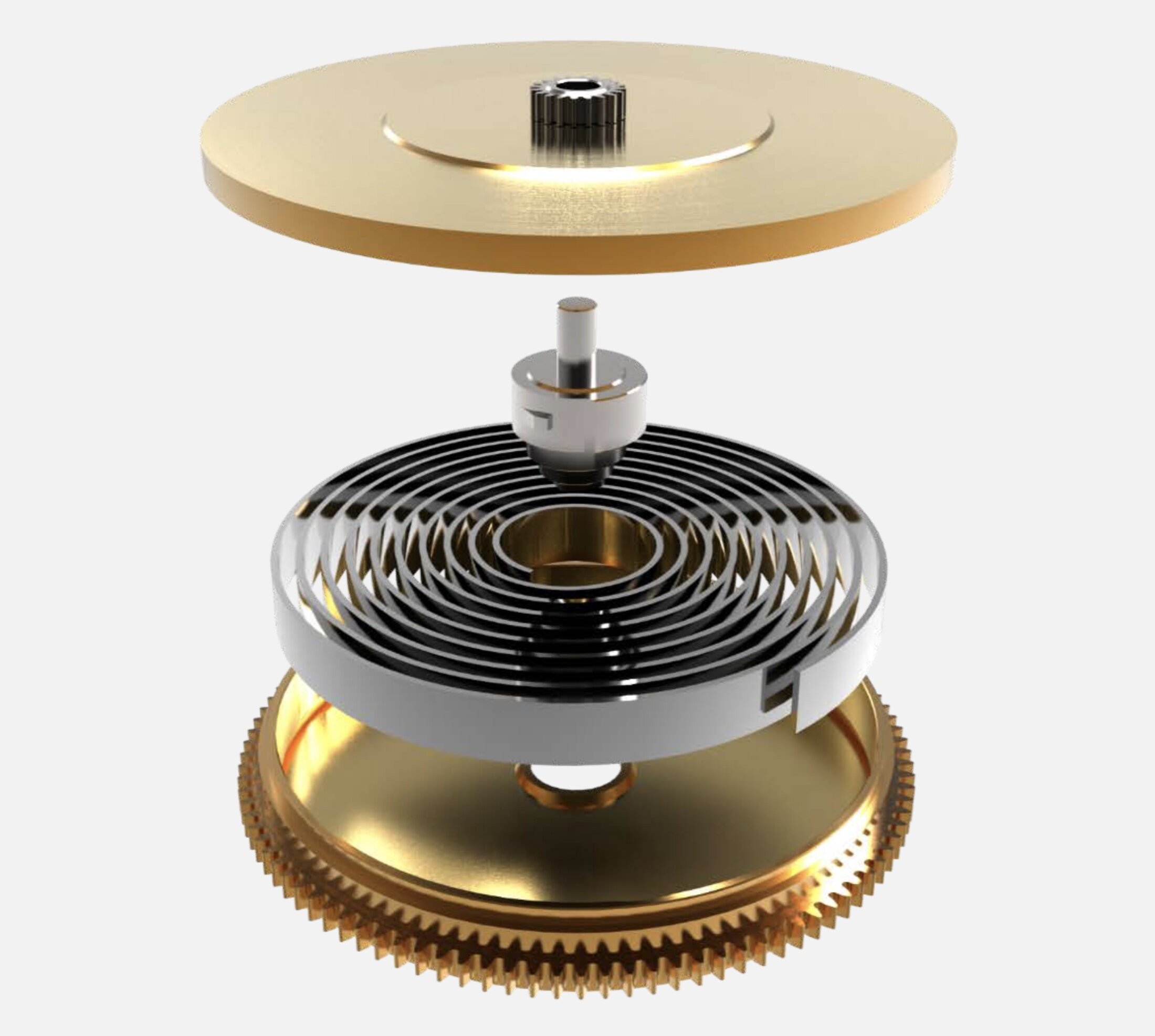
A virtual image of an exploded barrel (with an unfinished mainspring).
Step 1
The Material
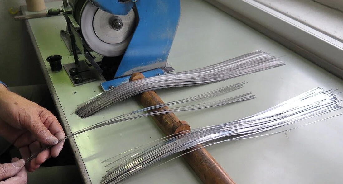
The first step in the process of making the spring is to receive the material which will be used to produce it. This particular alloy is made in Germany and delivered in diameters that correspond to the final dimensions of the different sized springs to be produced.

Each roll of material is destined for a different calibre.
The material is always received circular in cross-section.


Step 2
'Laminage' or Rolling
Rolling is a forming process in which the round wire is passed through 3 pairs of rollers to reduce the thickness to a specific rectangular dimension and to ensure uniform thickness throughout its length. Once the wire leaves the rollers, a diamond-tipped measurement system checks the thickness and height of the material. This system will automatically adjust the rollers to correct for any variations in the rolling process that is precise to 0.5microns which is equivalent to 0.0005mm. The minimum height is 0.6mm and the tallest mainspring is 3.5mm.

The rolling machine above required 12 months of adjustments and tuning until the desired results were consistently achieved.
Step 3
Cleaning
Once the full roll of wire has been through the 'Laminage' process which requires considerable oil between the rollers and the wire. It is then placed into a bath with cleaning solutions set at a specific temperature before being dried.

Step 4
Cutting and Stamping
The spring is cut into the specific length required, at the same time the eyes are cut for the arbor hook to catch onto. The eyes also facilitate the process of coiling the strips into springs.


Step 5
Polishing
The section of surface at the end of the automatic mainsprings that slides on the inside of the barrel walls, are manually polished. On large quantities of production this process is mechanically executed.


Step 6
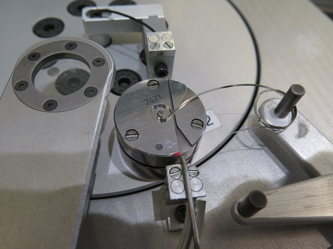
'Coquillonage' or Coiling
The strips of metal are now coiled into their definitive form. The form of the mainspring has changed considerably since the original conception of the mainspring several hundred years ago. The original springs were made from carbon steel and and when removed from the barrel resembled a classical spiral. The carbon steel would eventually weaken and break with fatigue. The power delivered by them was extremely uneven. Weak at the first wind and disproportionately strong at the final turn.
Many inventions were developed to balance out this variable power output during the early days of horology. Some like the fusee, would both limit which part of the mainspring could be used, avoiding the beginning and the end of the spring, using only the more consistent central length. As well as using a conical gearing system which would compensate further for the increasing power as the spring was wound. The modern mainspring, made from alloys that are more consistent and last longer than their predecessors, are coiled in a reverse form that allows for a more consistent power output than was originally developed.

The end of the strip with the eye is lead into a special tool which then curves the material into the form that will eventually sit onto the barrel arbor. Gauges are used to ensure the form is correct in shape and dimension.


After the centre of the mainspring is finished the reverse curve which can be seen in the first two images at the top of the page are generated.
Step 7
Heat treatment
The final springs go through a thermic process to guarantee the tensile strength of the spring. The stronger the springs, the more powerful the energy developed by the coiled spring.
Step 8
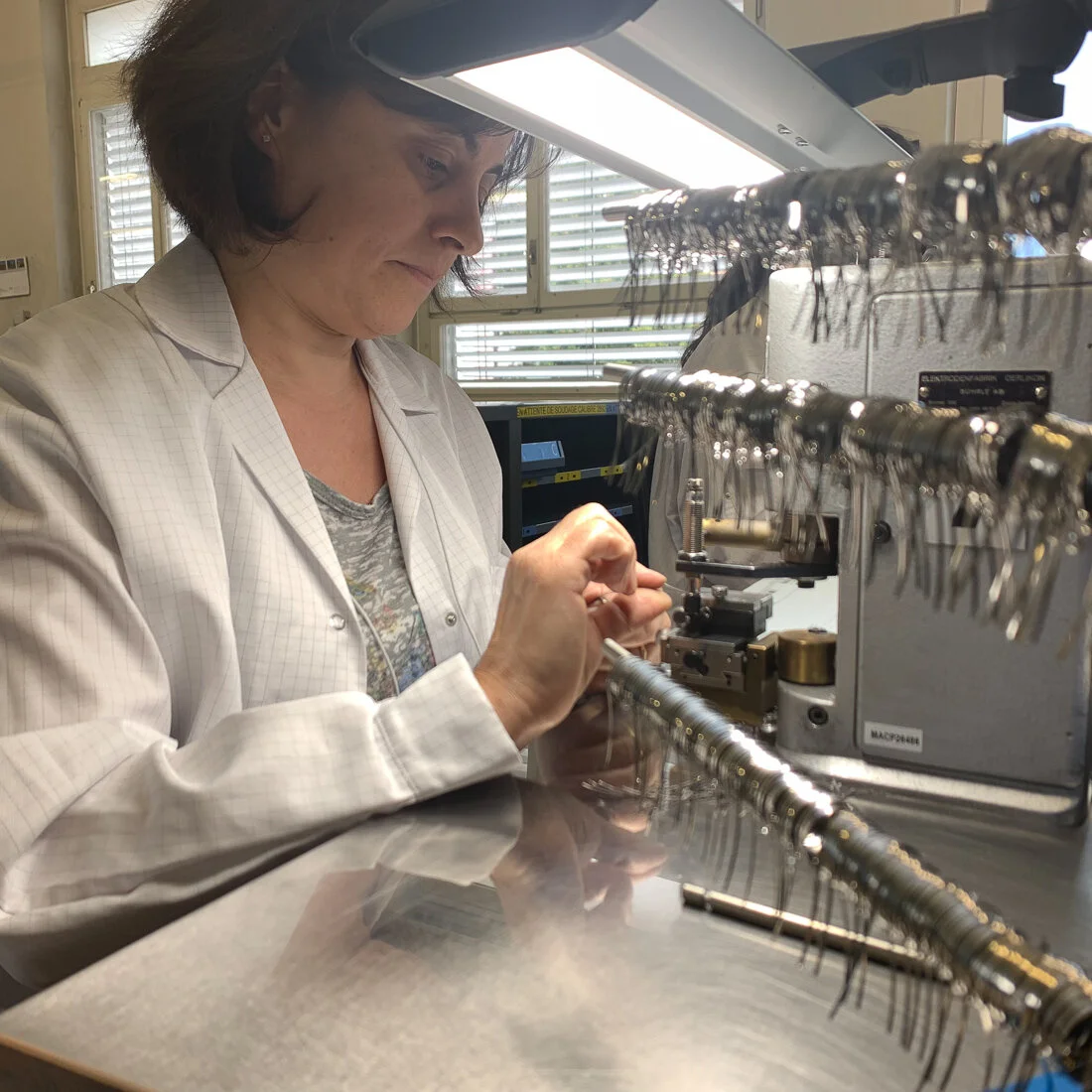
Spot welding
The majoirty of mainsprings have a bridal which either hook to the inside of the barrel or on automatic mainsprings will be on the inside of the last coil. There exists a further design similar to that found in clocks and marine chronometers where the end of the mainspring has an eye (like the one that hooks to the arbor) that fixes to the hook protruding from the inside of the barrel wall. With the exception of this style of mainspring, a bridal is added that is spot-welded in place.

The automatic bridles, 20% thicker than the mainspring.

The bridal being welded in place.

The mainsprings with the bridles attached.
Step 9
Lubrication of spring
Once the mainsprings are finished they are immersed into a tank containing teflon that covers the surface of the springs, the purpose is to reduce friction between the surfaces of the mainspring.

Step 10
Prepping the final mainspring
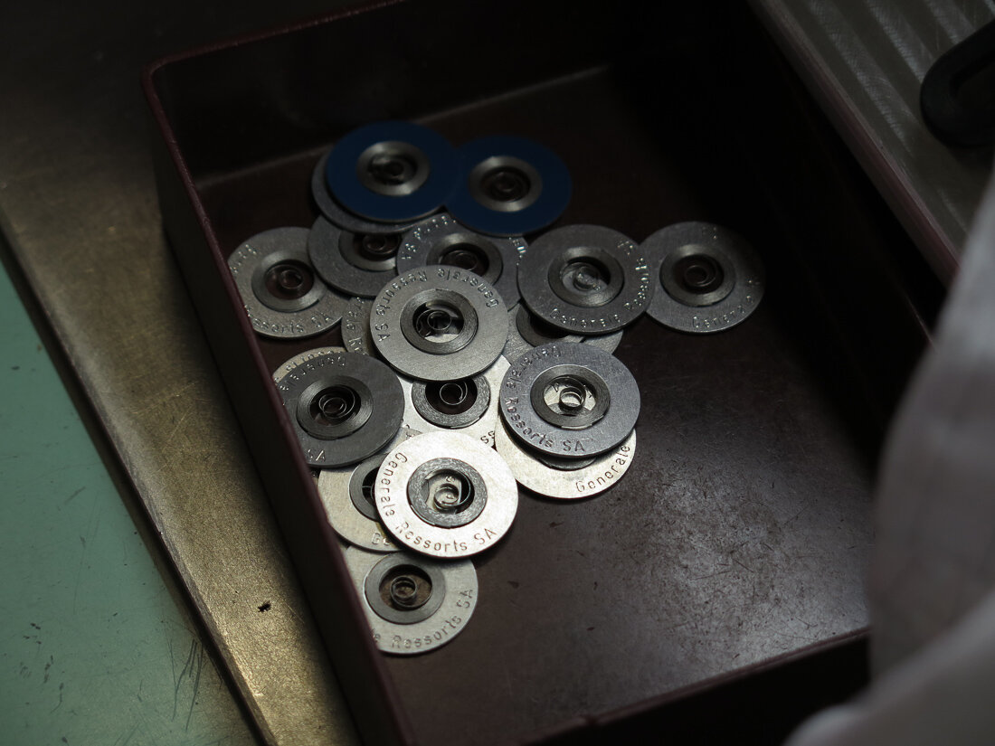
The mainspring is then wound to be placed either into an aluminium ring or the barrel drum.


On large productions of complete barrels which range into tens of thousands of units, advanced automations and robotics are used, some systems are fully automatic. The above is a semi-automatic system requiring an operator but producing large volumes of assembled barrels. The barrel, barrel caps, arbor and springs are all fed into the centre, lubricated and assembled. The end shakes are checked as soon as the complete barrel is assembled.
Step 11
Lubrication and Assembly
Arbor
The barrel arbors once cleaned and dried are placed in a small basket which in turn is suspended inside of a special lubrication machine, turned in a thick grease that has been heated to become liquified that covers the entire surface of the arbour. Centrifugal force causes supplementary liquid to be dispersed. Once they cool the consistency changes, becoming solid but remaining slippery.
Barrel
There are multiple systems incorporated in lubricating the barrels, specifically the inner barrel wall on automatic mainsprings that slide when full wound. Some companies who order complete barrels which is the most frequent form of order, have different systems of lubrication and the greases are added manually, to be aligned with the philosophy adopted within that company. Some orders which account for tens of thousands of units are either fully or semi-automated, below is a semi-automated system.

Graphite grease being applied to the inner barrel wall on an automatic barrel drum.
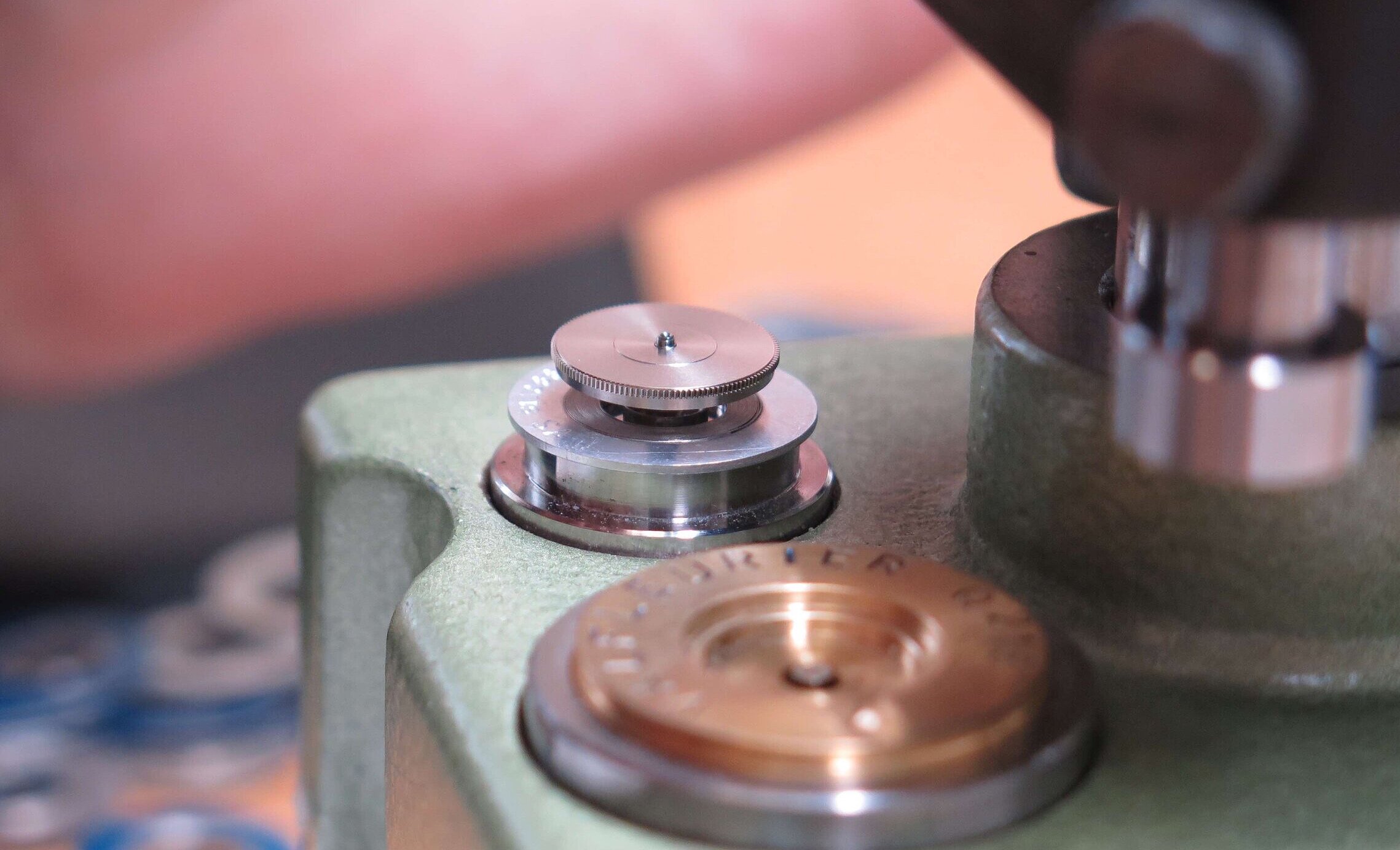
The barrel drum about to be pressed onto the mainspring, guided by the barrel arbor that sits on a small tube leading the assembly onto the mainspring. The the barrel arbor is in place the small tube falls through the press and is re-used.
Step 12
Quality control
Once the mainsprings are finished they are checked to ensure that the multiple criteria required are reached such as the exact quantity of torque developed. Also ensuring the torque is consistent and the assemblies do not stick at any point due to either incorrect tolerances, lubrication or faulty parts. Ensuring the slipping of the mainspring is regular and at the correct moment of torque. Samples of each mainspring are also tested to deconstruction by machines which accelerate their use to ensure the longevity of the springs.

Above 3 graphs showing different mainsprings. The green curves illustrate the mainspring being wound, the black curves the unwinding of the springs. The one to the left is faulty, showing uneven torque transmission, the two to the right are both correct.
Step 13
Delivery
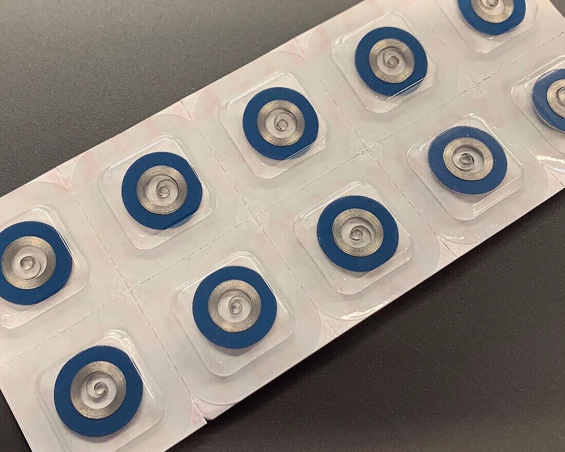
The final mainspring, depending on the client is delivered primarily either as 'Complete Barrels', or in aluminium rings to be fitted manually to the barrel at a later time. This can be in answer to aftersales service requirements or clients who prefer to execute the barrel assembly process themselves. The aluminium rings are coloured on one side as well as carrying a reference. The colour is to indicate which side should be viewed by the technician or watchmaker, who will fit the mainspring into the barrel, to assure it is placed correctly.

Summary
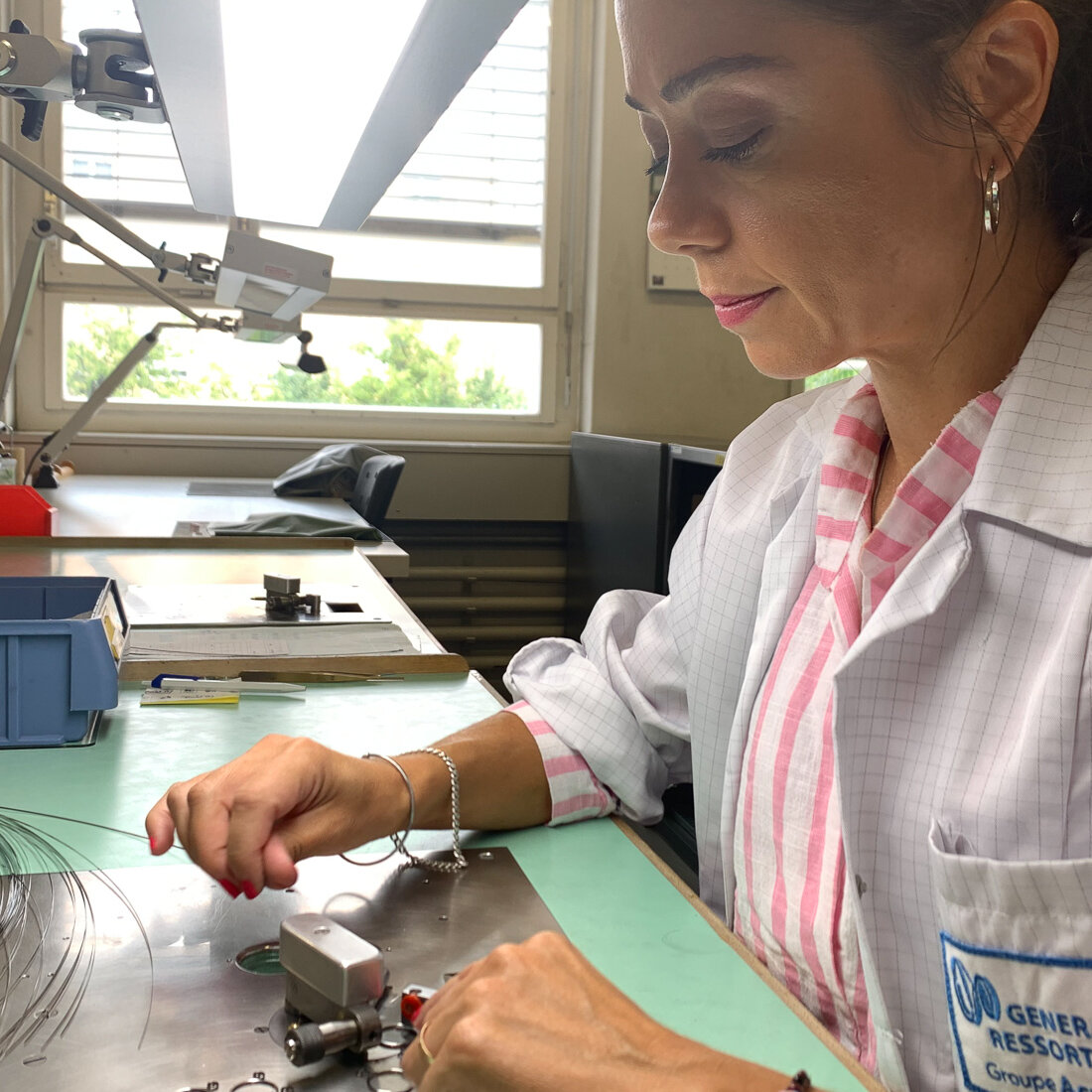
There are less than a hand full of mainspring manufactures in Switzerland producing millions of units per year for the industry. ‘Générale Ressorts’ were kind enough to open their doors to explain the process that makes the spring that lies in the heart of a mechanical watch. Despite the volume of their production, the diversity of executions implemented in the manufacturing process, high-lighted why it is so difficult to manufacture this one component and why so few companies are capable of doing it.
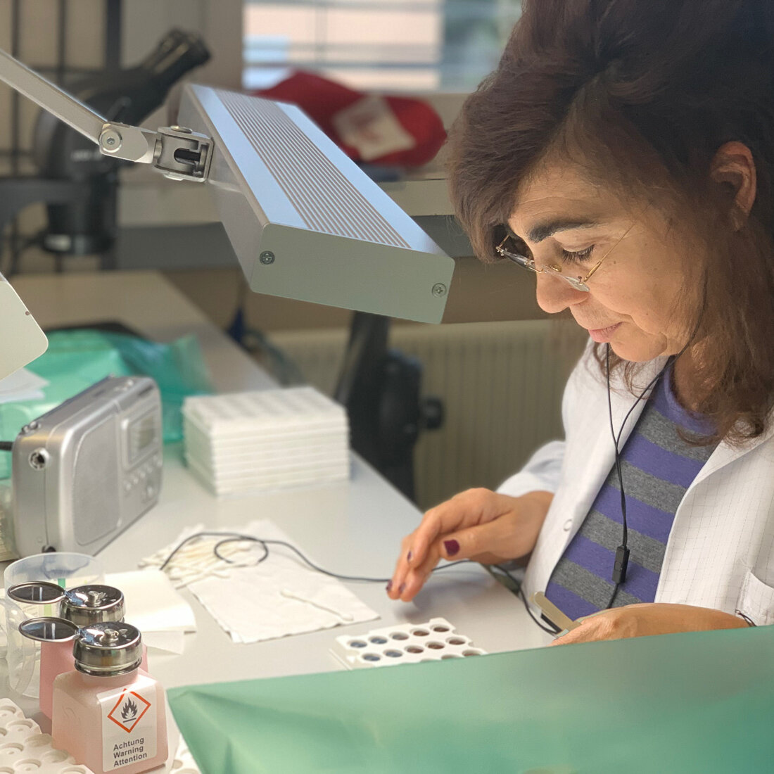
A few of the people involved in the process.


History
Générale Ressorts were founded in 1857. In 2009 they were purchased by the group Acrotec. The resulting merger into Acrotec has allowed Générale Ressorts to take steps to deliver to their clients the complete barrels in place of just the mainspring. The sister companies within the group generate additional competencies such as the manufacture of the barrels, arbours, decoration and treatments.
To learn more about Générale Ressorts