The Reason
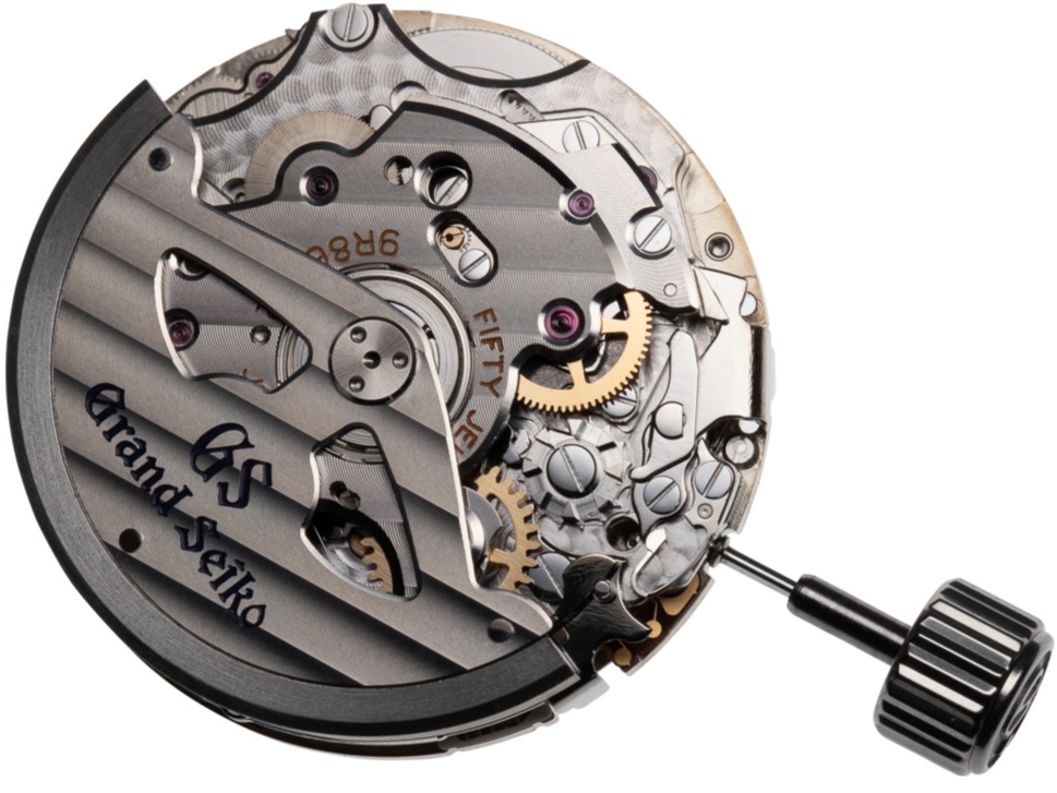
The Spring Drive Chronograph combines traditional historical elements from conventional horology such as the pillar wheel with Spring Drive’s electromagnetic time regulating system.
Introduction/functions
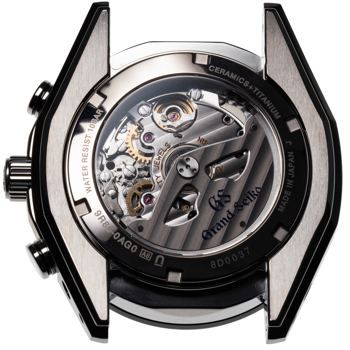
The Grand Seiko Black Ceramic SBGC221 is a Spring Drive chronograph with GMT, date, power reserve indication, and automatically wound. The power reserve lasts for 72 hours. Accuracy: ±1 second per day / ±15 seconds per month (average). The Chronograph records up to 12 hours with the minute and hour counters visible on the right hand side of the dial, central chronograph hand. The power reserve is set at 7 o'clock and the constant small seconds at 9 o’clock.
Technical Specifications
The movement caliber is 9R86. Column wheel chronograph. Number of jewels: 50. High-intensity titanium, (40% lighter than stainless steel), and zirconia ceramic case. Sapphire crystal with anti-reflective coating. Screw-down winding crown, water resistance: 10 bar/100 meters. Magnetic resistance: 4,800 A/m. Case size: diameter: 46.4mm, Thickness: 16.2mm.
Please move the cursor across the image below, (or by finger on a smart phone), to rotate the watch.
The bracelet removed showing the thick ceramic section integrated into the titanium case.
The case back with sapphire crystal is screwed in place using a 6 fingered key.
The movement is held in place by 2 large movement clamps that cross the movement ring and hook into the case centre. When removed (with the stem) the movement exits from the case back side.
Recto-verso of the movement with the dial removed.
Inclined view showing the Spring Drive layer of the calibre level with the stem. The upper layers are the chronograph and automatic mechanisms.
An exploded view of the movement illustrating the complexity of the calibre.
(Courtesy of Grand Seiko)
The rotor that winds up the mainspring is held onto the rotor arbor by a large threaded screw plate with 3 holes.
Recto-verso of the rotor weight. The external section of the rotor is made from tungsten carbide, the centre from brass
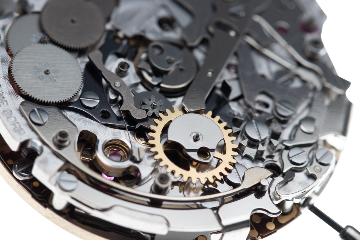
To the right of the image, is the column/pillar wheel which is activated by the pusher on the side of the case set at 2 o’clock.
The bridge supporting the rotor and upper pivots for the minute and hour recorders.
The ball race upon which the rotor turns is riveted into the bridge.
The rotor turns moving a piece called the ‘magic lever’ which drives the wheel shown at 5 o’clock on the image leading to the barrel.
The automatic winding system (developed in 1959 by Seiko) remains effective today and winds the mainspring when the rotor oscillates in both directions with the ‘magic lever’ pushing and pulling the transmission wheel as the rotor turns.
With the upper bridge removed more of the chronograph mechanism is visible.
The lower gold coloured wheel is the minute recorder, the higher the hour recorder.
The column wheel viewed between the minute and hour recorders.
The steel cam under the hour recorder is pushed by the hammer piece to reset it (and the other counters) to zero. The large flat disc under the cam acts as a guide for the hammer.
The next automatic bridge removed showing the indexing system for the minute recorder to the left of the minute recorder wheel. The hour recorder is no longer in place.
The lever at 5 o’clock is pushed by the start-stop button set at 2 o’clock on the case turning the column wheel.
The largest steel component is the hammer piece which has 3 flat heads which returns the 3 counters to zero when the 4 o’clock button is pressed.
Recto-verso of the hammers. The gold coloured eccentric plug (also made from copper beryllium) allows the minute hammer face to be adjusted independently of the other two faces.
The minute recorder wheel and hammers removed showing the remaining part of the chronograph.
In the centre of the image is the vertical clutch assembly upon which the chronograph hand sits. The clutch system when operated starts and stops the chronograph. The two grey levers either side of it function together and are controlled by the column wheel. When the column wheel turns by one tooth the two levers move, slicing into the vertical clutch disengaging it from turning.
The chronograph further dismantled.
The remaining chronograph pieces removed. The vertical clutch is held captive under the main bridge and can not be removed until the bridge is removed.
The two operating levers on the right are to activate and return to zero the chronograph. The large spring on the left indexes the column wheel. In the centre is the column wheel.
Recto-verso of the main chronograph plate supporting the majority of the chronograph mechanism.
Once the upper bridge is removed the vertical clutch chronograph wheel is visible and the lower Spring Drive section of the movement.
The chronograph mechanism is driven directly from the Spring Drive section of the calibre when activated through the vertical clutch.
The vertical clutch system partially removed from the base calibre.
The vertical clutch wheel.
Summary
The Spring Drive Chronograph combines traditional historical elements from conventional horology such as the pillar wheel, with Spring Drive’s electromagnetic time regulating system. In addition the combination of titanium and ceramic are congruent with the overall modern design of a new generation of Grand Seiko chronographs.




An explanation of how the Spring Drive mechanism works.
(Courtesy of Grand Seiko)
To learn more about Grand Seiko

